Recommend Products
-
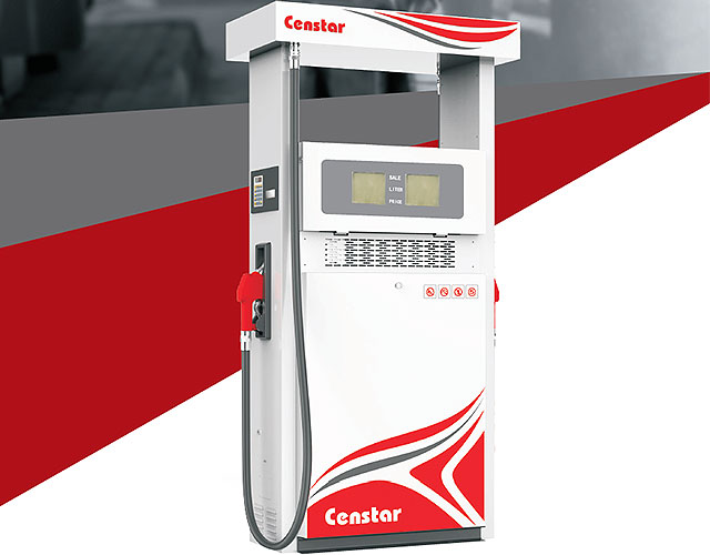
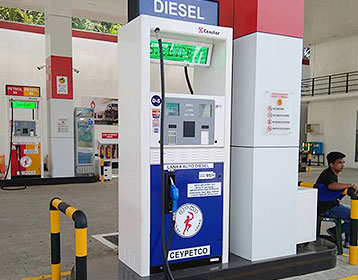
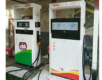
E-Man Series Fuel Dispenser
-
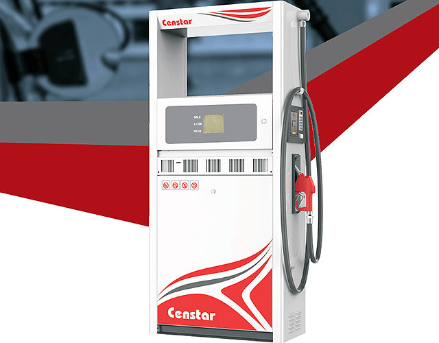
R-Man Series Fuel Dispenser
-
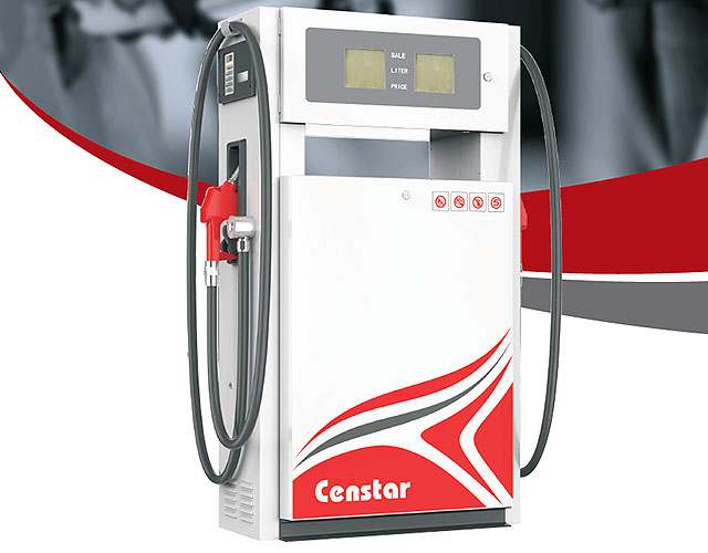
S-Man Series Fuel Dispenser
-
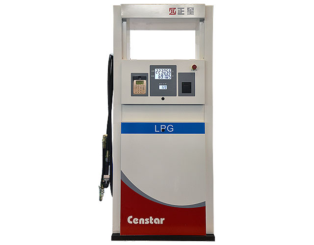
LPG dispenser
-
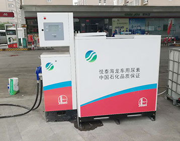
CNG Loading device / unloading device
-
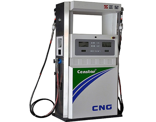
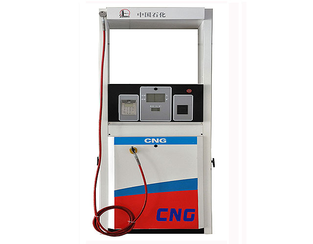
CNG Dispenser
-
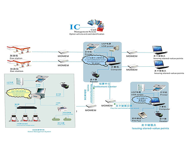
IC Card fuel station management system IC-FMS
-
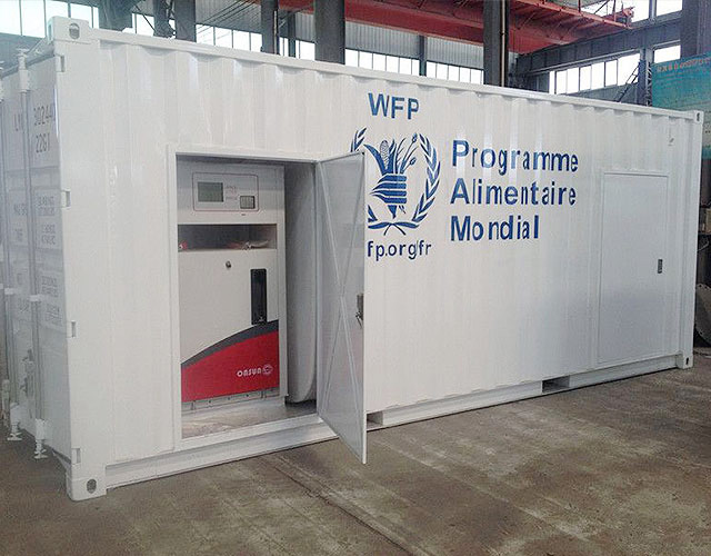
Censtar Mobile fuel station CSMF15(15000L)
-
centralized type (for diesel only) Management system of oil depot
PTS 1 fuel pump controller
Controller over mechanical fuel dispensers is intended to be used in connection with a control system for petrol station (POS system, cash register, OPT terminal, etc) to provide direct control over operation of electronic and mechanical fuel dispensers by controlling dispenser’s internal resources: motor, pulse sensor, nozzle, slowdown valve.
Wiring Diagram Book Schneider Electric
Square D 8501 Type NR Sockets, WELL GUARD® Pump Panels, Definite Purpose Contactors 8910, Square D NEMA Relay, Fractional Horsepower Starters, TeSys LR2K Overload Relays, TeSys GV3 Manual Starters and Protectors, TeSys GV7 Manual Starters and Protectors, Class 8903 Combination Lighting Contactors, NEMA Type S Motor Starters (8536 8736 8606), Type K Manual Switches,
Article 514 Motor Fuel Dispensing Facilities
Article 514 Motor Fuel Dispensing Facilities. By Mike Holt, for EC&M Magazine. Imagine how terrible it would be if you were putting gas in your company truck or your personal automobile, and the gas dispensing station erupted into a ball of fire.
COWAY CHP 06EL SERVICE MANUAL Pdf Download.
Circuit diagrams 8. Circuit diagrams 8 1 MAIN This document is Coway’s technical property. Only the person approved by the company may use this document. Coway co., Ltd Page 64: Button Switch Circuit diagrams 8 2 BUTTON SWITCH This document is Coway’s technical property.
SK700 II Fuel Dispenser Gilbarco Veeder Root Europe
Gilbarco Veeder Root’s advanced fuel retail technology is designed to improve your business. The most comprehensive dispenser available, the SK700 II is the culmination of the quality and expertise that have become Gilbarco Veeder Root’s trademarks.
SAMSUNG RF28HMEDBSR SERVICE MANUAL Pdf Download.
View and Download Samsung RF28HMEDBSR service manual online. FRENCH DOOR REFRIGERATOR. RF28HMEDBSR Refrigerator pdf manual download. Also for: Rf28hmedbww, Rf25hmedbsr, Rf25hmedbbc, Rf25hmedbww, Rf28hmedbbc.
Fuel Dispensers Q510 Tokheim TokheimTokheim
Dover Fueling Solutions Launches Tokheim Quantium™ 510M Fuel Dispenser Series. . Dover Fueling Solutions Exhibits at The Forecourt Show. Fuel Dispensers Q510 Fuel Dispenser . Overview Multiproduct dispenser 6 6 4 LCD, 7 7 5 LCD or 17" VGA media display Full Hose Retraction Semi Hose Retraction TQM as standard

Fuel Pump Electrical Circuits Description and Operation
This is a free ScannerDanner Premium video. Recorded during my Engine Performance class at Rosedale Technical College. I have many more videos just like this available only on ScannerDanner
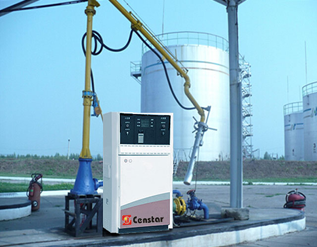
SAIKE FUEL DISPENSER
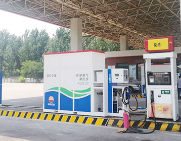
a)The horizon distance between fuel dispenser and under ground tank no more than 30m(except submersible fuel dispenser). The vertical distance between the lowest lever of the tank and the center of the combined pump no more than 4m. b)The base of the fuel dispenser must installed on the cement basis, and fasten by bolts.
Electric Motor & Wiring Diagram Censtar
When diagnosing a faulty automotive motor it is often impossible not to perform major disassembly, such as the fuel pump itself. Learn the procedures that'll save time
How to Obtain a Wiring Diagram or Schematic
A wiring diagram (mini manual) is included with each appliance. If you are in need of a replacement wiring diagram, you can determine where to find it on your appliance by visiting: Wiring Diagram Locations. Note: Some window air conditioners, dehumidifiers, compact refrigerators, and small countertop microwaves do not have wiring diagrams.
CHAPTER 3 COMPONENTS OF THE RETAIL MOTOR FUEL
COMPONENTS OF THE RETAIL MOTOR FUEL DISPENSING SYSTEM CHAPTER OBJECTIVES prevents fuel from draini ng from the discharge hose, assuring delivery of the full metered amount of fuel. a m otor driven pum p furnishes the hy drauli c pressure that moves fuel from the storage tank to the dispenser, through the m etering de vice, and to the
Electrical Schematic Circuit Wiring Diagrams
The following electrical wiring diagram applies for Yamaha Raptor ATV series. This manual covers all the electrical components of the vehicle which are main switch, front brake switch, indicator lights, circuit breaker, park switch, clutch switch, handlebar switch, fuse, starter relay, tail/brake light, CDI unit, battery, ignition coil, headlight, fan, etc.
Simple Single LED 'Low Fuel Light' All About Circuits
Simple Single LED 'Low Fuel Light' Reply to Thread. Discussion in 'The Projects Forum' started by nizzkid, This is because as it stand the fuel guage sits at 'full' 90% of the time anyway, its not till the last 30km or so that needle moves down. Your looking for a comparator circuit if all you want is a low fuel indication. The problem
Electrical Safety for Motor Fuel Dispensing Facilities
Since the LVDD is connected in series with these circuits, it will disconnect circuits for audio, video, card reader, loyalty program, and other communications circuits when the ac circuit disconnect for the dispenser is opened or when the emergency station control disconnect is activated.
BC337 Circuit Wiring Diagrams
From circuit diagram Figure 1. Meanwhile, a sensor does not touch water. Though we will slide a S1 switch together and electrical current in to this circuit. Figure 1 the perfect circuit diagram of a simple high level water alarm. As Figure 2 is The virtualwork while water level is below the sensor point.
Electric Fuel Gauges
ELECTRIC FUEL GAUGES. TESTING A GAUGE Click to jump to this section.. THERMAL TYPE GAUGE. Beetles were first sold with electric fuel gauges beginning with the 1968 model year. Karmann Ghias and Buses had them even before this. The gauge used on the Beetle from '68 onward is a thermally actuated design. It is not a new concept; Ford used gauges similar to this as early as the
PROJECT STANDARDS AND SPECIFICATIONS piping and in
The drafting must be of sufficiently high quality to maintain legibility when the drawing is reduced to an A3 size sheet. 2. Drawings sheet sizes Diagrams should be shown on A0 size (841 mm × 1189 mm). A1 size (591 mm × 841 mm) may be used for simple P&IDs and UDFDs as per Company’s approval.
LIQUID FUEL DISPENSER & PUMP SERVICE MANUAL
term dispenser to refer to both Compac dispensers and pumps, unless otherwise specified. In general, the term liquid fuel refers to hydrocarbons, that is, petrol and diesel. Operating Parameters Compac liquid fuel dispensers are designed to meter petrol and diesel under the following conditions: The liquid pressure range is from 0.5 20mPa
Grizzly 700 Fuel Diagram Wiring Diagram Database
Grizzly 700 fuelpump fuel tank for yamaha grizzly 700 usa sales region yamaha grizzly 700 yfm7fgpw fuel tank diagram partzilla 501parts yamaha grizzly 700 eps se yfm700psfs fuel tank parts yamaha grizzly 700 fuse box circuit diagram maker yamaha grizzly 700 technical specifications ultimate specs yamaha grizzly 700 fi owner s manual download
USB IF USB 2.0 Electrical Compliance Test Specification
4 3.4 Packet Parameters EL_21 The SYNC field for all transmitted packets (not repeated packets) must begin with a 32 bit SYNC field. Reference documents: USB 2.0 Specification, Section 8.2. Test description: Section 4.5.1 EL_22 When transmitting after receiving a packet, hosts and devices must provide an inter packet gap of at least 8 bit times and not more than 192 bit times.
Fuel Monitoring and Electronics control of Dispenser for
A. Selecting of fuel Pump Pipe Length between pump and dispenser 100ft x = Pipe length between dispenser and oil gun 10ft x = The height of the ground tank = 13ft must be taken in this design. Total height of the system = tank height + height from gun to the ground = 13 + 4 = 17ft x =
C13 Fuel Filter Base Wiring Diagram Database
C13 upgrades mpg tips and hp tips truckersreport caterpillar fuel filter base ebay i m working on a cat c13 engine the truck came in after fuel filter bases for sale mylittlesalesman caterpillar base as fuel filter cat c13 parts accessories ebay my truck has a cat c13 acert under heavy acceleration. 2019 In Wiring Diagram 186 views
 Message
 tel
tel Inquiry